Page 624 - Hydrover-hydraulic-integrated-circuits-catalogue
P. 624

Multifunctional integrated circuits  97 SERIES

                                                                                                     H97101

                                                     Ordering code
                     H 9      7    1   0    1   _    _    -   _    _   -    _   _    -   _    _   _


       Hydrover                                                                                     Solenoid valve
       product                                                                                                 coil Dimensions in mm
                                                                                                      connection *
       Product series                                                                               1 =  DIN 43650
       97 series - Multifunctional                                                                        ISO 4400
       integrated circuits

                                                                                                    Solenoid valve
       Product ID                                                                                     coil voltage *
                                                                                             OB =          12V DC
                                                                                             OC =          24V DC
       Manifold material                                                                     OD =          48V DC
       Aluminium                              =A                                             OU =        110V RAC
       Steel                                  =S                                             AH =        230V RAC


       Section type                                                                                 Solenoid valve
       Inlet                                      = E                                             manual override *
       Intermediate                               =  II                        E0 =                         Without
       Closing                                    = C                          EV =                          Screw


       Relief valve adjustment type on R *                                                  Relief valve adjustment
       Screw                                              = S                                 pressure range on R *
       Knob                                               = K       1 =                                  35-140 bar
                                                                    2 =                                  70-280 bar
                                                                    3 =                                 140-420 bar
                                                                    3 =                        35-350 bar (adj. knob)


        N° Description                                                                                       Q.ty
        1   TPCLOR7/16”UNF on the inlet section (T)                                                            1
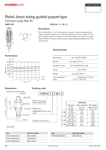
        2   Bosch Rexroth relief valve on R VSPN-10A * depicted with screw adjustment                          1
        3   Bosch Rexroth coil D36 - CLASS H DIN 43650 ISO 4400 *                                              1
        4   Connector DIN 43650 ISO 4400                                                                       1
        5   Bosch Rexroth solenoid valve OD.15.05.21-Y-00000 depicted without manual override *                1

        6   TPCLG-38G on the inlet section (P)                                                                 1
        7   Ø 8,5 through hole for tie rod                                                                     3
        8   TPCLG8X1 on the inlet section (LS)                                                                 1
        9   HCMM03-S3 50-350 bar anti-shock valve on the inlet plate, 0489A2008500000 plug on the other sections.  1
        10 Flow regulator                                                                                      1
        11 TPCLG8X1 on the closing section, OR 109 Ø i. 9,13 c. s.  2,62 on the other sections (LS)            1
        12 TPCLG-38G on the closing section, OR 3075 Ø i. 18.72 c. s.  2,62 on the other sections (P)          1
        13 TPCLOR7/16”UNF on the closing section, OR 3056 Ø i. 13.95 c. s.  2,62 on the other sections (T)     1
        14 TPCLG-34G on the intermediate and closing sections (P)                                              1
        15 TPCLG-14G on the inlet and intermediate sections (LS OUT), on all sections (LS IN)                  1

        16 TPCLG-12G on the intermediate and closing sections (T)                                              1
            TPCN 6 under the TPCLG-M8X1 on intermediate and closing sections. To add on the inlet section if a LS IN   1
        17
            is connected.
       * for complete technical information, click on the blue link.
       624                                             General catalogue                               July 2025 edition
   619   620   621   622   623   624   625   626   627   628   629